| Items |
 PKE543AC 1.65 in. (42 mm) PKE Series 5-Phase Stepper Motor (AC Input) Web Price $83.00
|
PKE544AC 1.65 in. (42 mm) PKE Series 5-Phase Stepper Motor (AC Input) Web Price $84.00
|
PKE545AC 1.65 in. (42 mm) PKE Series 5-Phase Stepper Motor (AC Input) Web Price $92.00
|
 PKE543AC-HS50 1.65 in. (42 mm) PKE Series 5-Phase Harmonic Gear Stepper Motor (Gear Ratio: 50:1) (AC Input) Web Price $857.00
|
PKE543AC-HS100 1.65 in. (42 mm) PKE Series 5-Phase Harmonic Gear Stepper Motor (Gear Ratio: 100:1) (AC Input) Web Price $857.00
|
|||||
| Frame Size | 1.65 in42 mm | |||||||||
| Motor Length | 1.34 in.34 mm | 1.57 in.40 mm | 1.81 in.46 mm | 1.34 in.34 mm | 1.34 in.34 mm | |||||
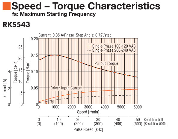
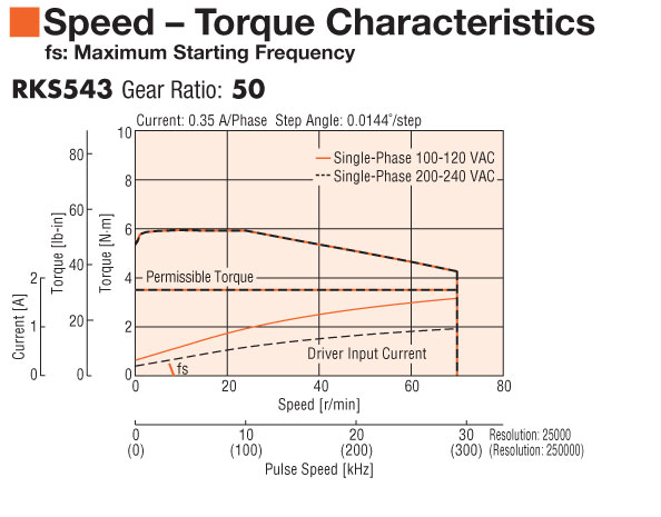
| Speed-Torque Characteristics |
 |
 |
 |
 |
 |
|||||
| Holding Torque | 19.8 oz-in0.14 N·m | 29 oz-in0.21 N·m | 38 oz-in0.27 N·m | 480 oz-in3.5 N·m | 704 oz-in5 N·m | |||||
| Type | Standard | Standard | Standard | Geared | Geared | |||||
| Shaft/Gear Type | Round Shaft with Flat (No Gearhead) | Round Shaft with Flat (No Gearhead) | Round Shaft with Flat (No Gearhead) | Harmonic Gear | Harmonic Gear | |||||
| Gear Ratio (X:1) | 50 :1 | 100 :1 | ||||||||
| Cable Direction | ||||||||||
| Backlash | ||||||||||
| Encoder Resolution | ||||||||||
| Shaft | Single | |||||||||
| Electromagnetic Brake | Not Equipped | |||||||||
| Current | 0.35 A | |||||||||
| Step Angle | 0.72 ° | 0.72 ° | 0.72 ° | 0.0144 ° | 0.0072 ° | |||||
| Permissible Speed Range (r/min) | 0 ~ 70 | 0 ~ 35 | ||||||||
| Rotor Inertia | 0.164 oz-in²30x10-7 kg·m² | 0.26 oz-in²47x10-7 kg·m² | 0.35 oz-in²64x10-7 kg·m² | 0.26 oz-in²47x10-7 kg·m² | 0.26 oz-in²47x10-7 kg·m² | |||||
| Lost Motion | 1.5 arc min maximum | 1.5 arc min maximum | ||||||||
| Permissible Overhung Load | 0 in. from Shaft End = 7.8 lb0.2 in. from Shaft End = 9.9 lb0.39 in. from Shaft End = 13 lb0.59 in. from Shaft End = 19.1 lb0 mm from Shaft End = 35 N5 mm from Shaft End = 44 N10 mm from Shaft End = 58 N15 mm from Shaft End = 85 N | 0 in. from Shaft End = 7.8 lb0.2 in. from Shaft End = 9.9 lb0.39 in. from Shaft End = 13 lb0.59 in. from Shaft End = 19.1 lb0 mm from Shaft End = 35 N5 mm from Shaft End = 44 N10 mm from Shaft End = 58 N15 mm from Shaft End = 85 N | 0 in. from Shaft End = 7.8 lb0.2 in. from Shaft End = 9.9 lb0.39 in. from Shaft End = 13 lb0.59 in. from Shaft End = 19.1 lb0 mm from Shaft End = 35 N5 mm from Shaft End = 44 N10 mm from Shaft End = 58 N15 mm from Shaft End = 85 N | 0 in. from Shaft End = 40 lb0.2 in. from Shaft End = 49 lb0.39 in. from Shaft End = 60 lb0.59 in. from Shaft End = 81 lb0.79 in. from Shaft End = 114 lb0 mm from Shaft End = 180 N5 mm from Shaft End = 220 N10 mm from Shaft End = 270 N15 mm from Shaft End = 360 N20 mm from Shaft End = 510 N | 0 in. from Shaft End = 40 lb0.2 in. from Shaft End = 49 lb0.39 in. from Shaft End = 60 lb0.59 in. from Shaft End = 81 lb0.79 in. from Shaft End = 114 lb0 mm from Shaft End = 180 N5 mm from Shaft End = 220 N10 mm from Shaft End = 270 N15 mm from Shaft End = 360 N20 mm from Shaft End = 510 N | |||||
| Permissible Thrust Load | 0.56 lb2.50 N | 0.69 lb3.10 N | 0.83 lb3.70 N | 49 lb220 N | 49 lb220 N | |||||
| Permissible Moment Load | ||||||||||
| Safety Standards | UL CE | |||||||||
|
|
||||||||||