![]()
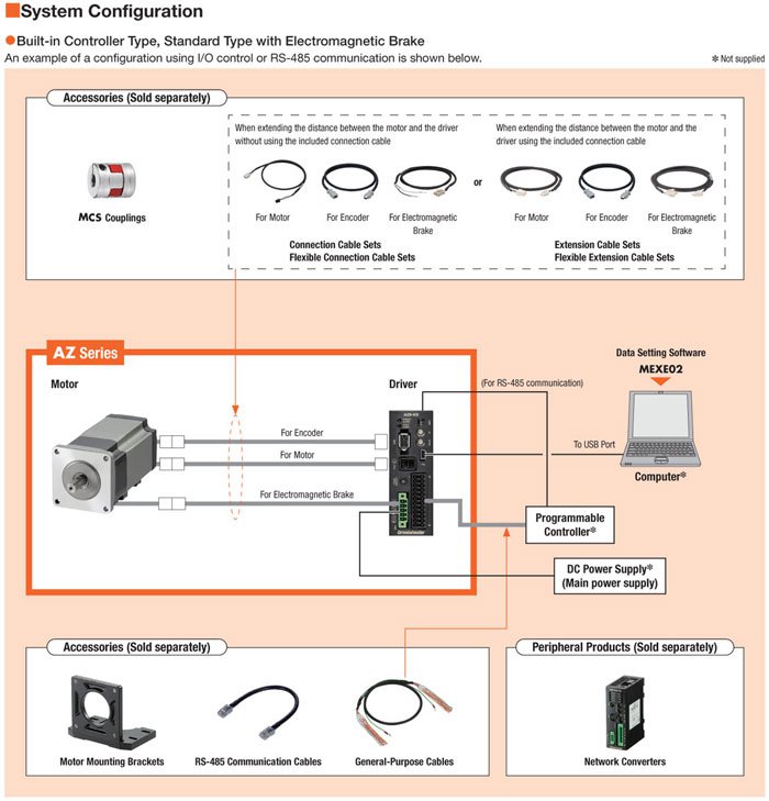
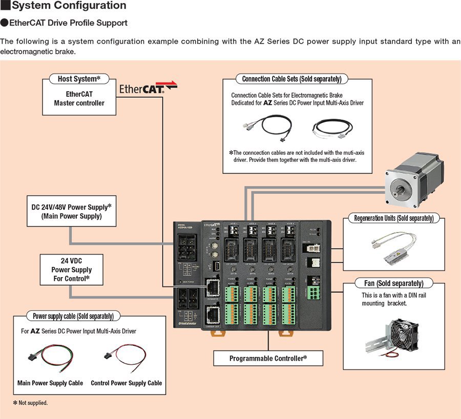
The αSTEP AZ Series stepper motor offers closed loop control, substantially reduces heat generation from the motor and by incorporating the newly developed Mechanical Absolute Encoder, absolute-type positioning is available, without battery back up or external sensors to buy.
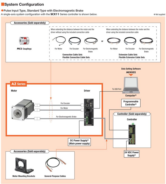
- Requires αSTEP AZ Series Driver
*Connection Cables required (sold separately)
| Lead Time1 | - {Contact your local sales office for more information.} |
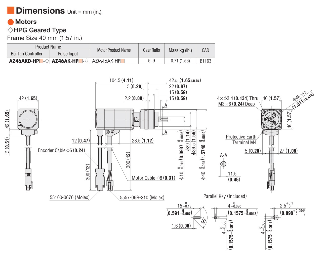
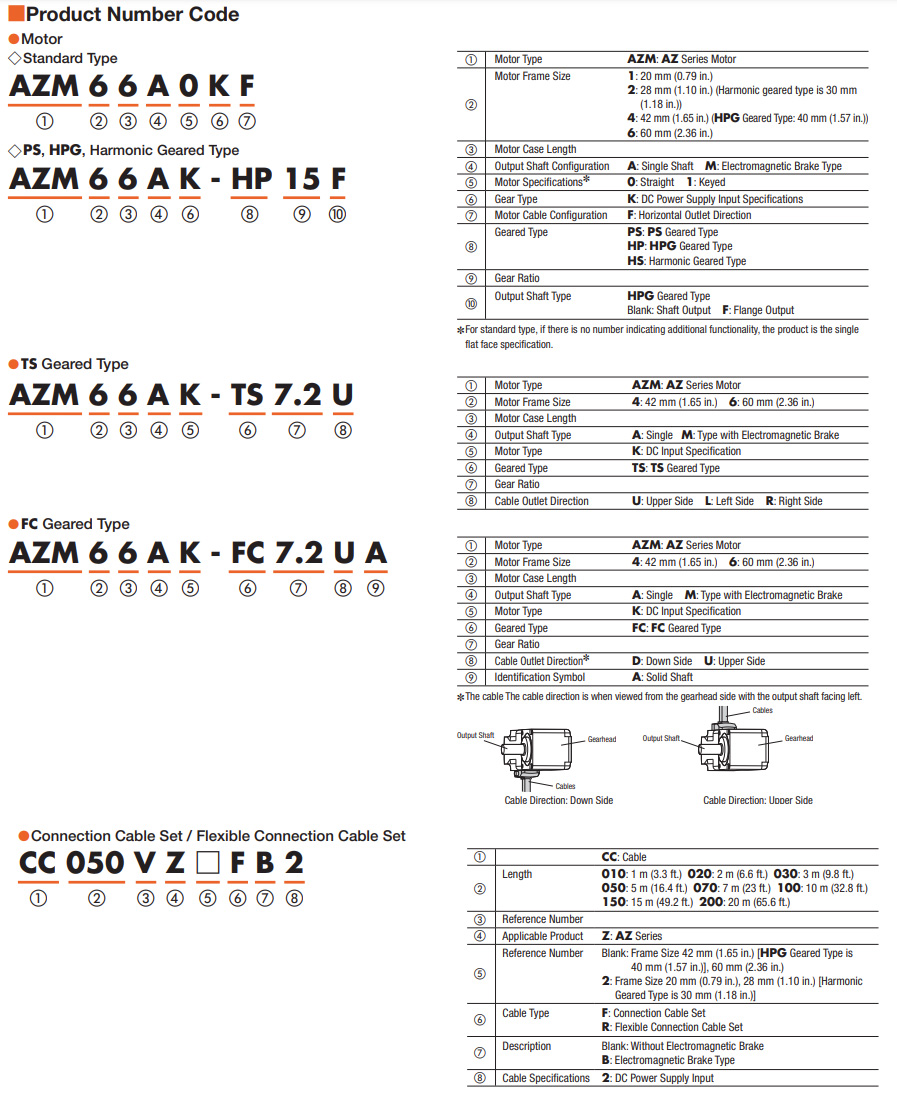
Frame Size |
- 1.57 in40 mm |
Motor Length |
- 4.11 in.104.50 mm |
Driver Voltage Input Power |
- DC |
Speed-Torque Characteristics |
-
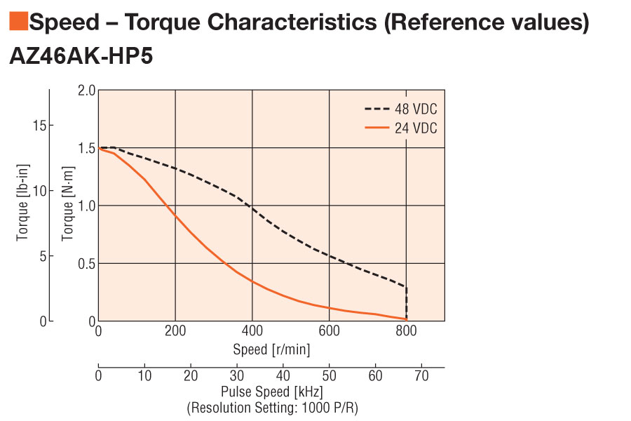 Speed - Torque Characteristics |
Holding Torque |
- 212 oz-in1.5 N·m |
Holding Torque at Motor Standstill |
- 106 oz-in0.75 N·m |
Type |
- Mechanical Absolute Encoder |
Shaft/Gear Type |
- Harmonic Planetary Gear |
Gear Ratio (X:1) |
- 5 :1 |
Backlash |
- 3 arc min (0.05°) |
Shaft |
- Single |
Electromagnetic Brake |
- Not Equipped |
Resolution (Resolution Setting: 1000 P/R) |
- 0.072 °/Pulse |
Permissible Speed Range (r/min) |
- 0 ~ 800 |
Rotor Inertia |
- 0.30 oz-in²55x10-7 kg·m² |
Stop Position Accuracy |
- ±4 arc minutes (±0.067º) |
Shaft Runout |
- 0.05 mm (0.002 in.) T.I.R. |
Concentricity |
- 0.075 mm (0.003 in.) T.I.R. |
Perpendicularity |
- 0.075 mm (0.003 in.) T.I.R. |
Permissible Overhung Load |
- 0 in. from Shaft End = 33 lb0.2 in. from Shaft End = 38 lb0.39 in. from Shaft End = 42 lb0.59 in. from Shaft End = 51 lb0.79 in. from Shaft End = 60 lb0 mm from Shaft End = 150 N5 mm from Shaft End = 150 N10 mm from Shaft End = 190 N15 mm from Shaft End = 230 N |
Permissible Thrust Load |
- 96 lb430 N |
RoHS Compliant |
- These products do not contain substances that exceed the regulation values in the RoHS Directive. |
Safety Standards |
- CE |
CE Marking |
- EMC Directives |
California Proposition 65 |
-
⚠ CA WARNING Cancer risk from exposure to Nickel. See www.P65Warnings.ca.gov Risk of reproductive harm from exposure to Di-n-hexyl phthalate (DnHP). See www.P65Warnings.ca.gov Risk of cancer and reproductive harm from exposure to Di(2-ethylhexyl phthalate (DEHP). See www.P65Warnings.ca.gov See "?" or copy/paste www.P65Warnings.ca.gov in your browser. |
Insulation Class |
- Class B [130ºC (266ºF)] |
Insulation Resistance |
-
100 MΩ or more when 500 VDC megger is applied between the following places: Case - Motor and sensor windings |
Dielectric Strength |
-
Sufficient to withstand the following for 1 minute: Case - Motor and sensor windings 1.5 kVAC 50 Hz or 60 Hz |
Ambient Temperature |
- 0 ~ 40ºC (32 ~ 104ºF) (non-freezing) |
Ambient Humidity |
- 85% or less (Non-condensing) |
Operating Atmosphere |
- Use in an area without corrosive gases and dust. The product should not be exposed to water, oil or other liquids. |
Degree of Protection |
- IP66 (excluding the mounting surface and connector) |
|
|
|
|
|
|
|
|
- 1 Quoted Ship Date for orders placed before 12:00 pm PST. Quantities may affect Shipping Date.