| Items |
 RK543AA Microstep Stepper Motor System (Single-Phase 100-115 VAC) Web Price Request Quote
|
RK543BA Microstep Stepper Motor System (Single-Phase 100-115 VAC) Web Price Request Quote
|
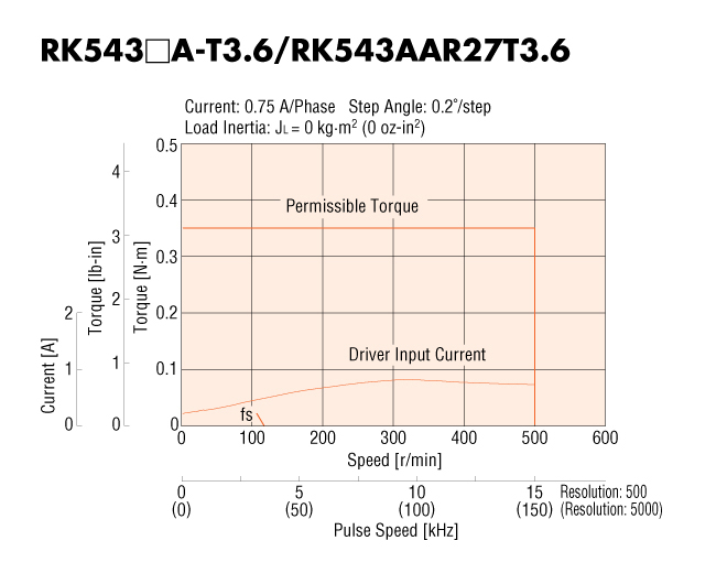
 RK543AA-T3.6 Microstep Stepper Motor System (Single-Phase 100-115 VAC) Web Price Request Quote
|
RK543AA-T7.2 Microstep Stepper Motor System (Single-Phase 100-115 VAC) Web Price Request Quote
|
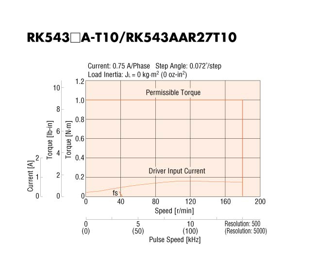
RK543AA-T10 Microstep Stepper Motor System (Single-Phase 100-115 VAC) Web Price Request Quote
|
|||||
| Frame Size | 1.65 in42 mm | |||||||||
| Speed-Torque Characteristics |
 Graph |
 Graph |
 Graph |
 Graph |
|||||
| Holding Torque | 18.4 oz-in0.13 N·m | 18.4 oz-in0.13 N·m | 48 oz-in0.35 N·m | 98 oz-in0.7 N·m | 141 oz-in1 N·m | |||||
| Type | Standard | Standard | Geared | Geared | Geared | |||||
| Shaft/Gear Type | Round Shaft (No Gearhead) | Round Shaft (No Gearhead) | Taper Hobbed Gear | Taper Hobbed Gear | Taper Hobbed Gear | |||||
| Gear Ratio (X:1) | 3.6 :1 | 7.2 :1 | 10 :1 | |||||||
| Backlash | 2 arc min (0.034º) | 10 arc min (0.17º) | 10 arc min (0.17º) | |||||||
| Shaft | Single | Double | Single | Single | Single | |||||
| Power Supply | Single-Phase 100-115 VAC | |||||||||
| Current | 0.75 A | |||||||||
| Basic Step Angle | Microstep- 0.00288º ~ 0.72º | Microstep- 0.00288º ~ 0.72º | Microstep- 0.0008º ~ 0.2º | Microstep- 0.0004º ~ 0.1º | Microstep- 0.000288º ~ 0.072º | |||||
| Permissible Speed Range (r/min) | 0 ~ 500 | 0 ~ 250 | 0 ~ 180 | |||||||
| Rotor Inertia | 0.191 oz-in²35x10-7 kg·m² | |||||||||
| Lost Motion | ||||||||||
| Encoder Output | ||||||||||
| Safety Standards | UL CSA (driver only) EN CE | |||||||||
| Permissible Overhung Load | 0 in. from Shaft End = 4.5 lb0.2 in. from Shaft End = 5.6 lb0.39 in. from Shaft End = 7.6 lb0.59 in. from Shaft End = 11.7 lb0 mm from Shaft End = 20 N5 mm from Shaft End = 25 N10 mm from Shaft End = 34 N15 mm from Shaft End = 52 N | 0 in. from Shaft End = 4.5 lb0.2 in. from Shaft End = 5.6 lb0.39 in. from Shaft End = 7.6 lb0.59 in. from Shaft End = 11.7 lb0 mm from Shaft End = 20 N5 mm from Shaft End = 25 N10 mm from Shaft End = 34 N15 mm from Shaft End = 52 N | 0 in. from Shaft End = 2.2 lb0.2 in. from Shaft End = 3.1 lb0.39 in. from Shaft End = 4.5 lb0.59 in. from Shaft End = 6.7 lb0 mm from Shaft End = 10 N5 mm from Shaft End = 14 N10 mm from Shaft End = 20 N15 mm from Shaft End = 30 N | 0 in. from Shaft End = 2.2 lb0.2 in. from Shaft End = 3.1 lb0.39 in. from Shaft End = 4.5 lb0.59 in. from Shaft End = 6.7 lb0 mm from Shaft End = 10 N5 mm from Shaft End = 14 N10 mm from Shaft End = 20 N15 mm from Shaft End = 30 N | 0 in. from Shaft End = 2.2 lb0.2 in. from Shaft End = 3.1 lb0.39 in. from Shaft End = 4.5 lb0.59 in. from Shaft End = 6.7 lb0 mm from Shaft End = 10 N5 mm from Shaft End = 14 N10 mm from Shaft End = 20 N15 mm from Shaft End = 30 N | |||||
| Permissible Thrust Load | 3.3 lb15 N | 3.3 lb15 N | 3.3 lb15 N | |||||||
| Permissible Thrust Load | The permissible thrust load shall be no greater than the motor mass. | The permissible thrust load shall be no greater than the motor mass. | ||||||||
| Current per Phase (A/phase) | ||||||||||
| Motor Connection Type | ||||||||||
| Connection Type | ||||||||||
| Lead Wires | ||||||||||
| Lead Time (Legacy) | ||||||||||
|
|
||||||||||