| Items |
 AZ46AAD AlphaStep Battery-Free, Absolute Sensor Stepper Motor and Driver Package with Built-in Controller Web Price Request Quote
|
 AZ46MAD AlphaStep Battery-Free, Absolute Sensor Stepper Motor and Driver Package with Built-in Controller Web Price Request Quote
|
 AZ46AAD-TS3.6 AlphaStep Battery-Free, Absolute Sensor Stepper Motor and Driver Package with Built-in Controller Web Price Request Quote
|
AZ46AAD-TS7.2 AlphaStep Battery-Free, Absolute Sensor Stepper Motor and Driver Package with Built-in Controller Web Price Request Quote
|
AZ46AAD-TS10 AlphaStep Battery-Free, Absolute Sensor Stepper Motor and Driver Package with Built-in Controller Web Price Request Quote
|
|||||
| Frame Size | 1.65 in42 mm | |||||||||
| Motor Length | 2.76 in.70 mm | 3.98 in.101 mm | 3.98 in.101 mm | 3.98 in.101 mm | 3.98 in.101 mm | |||||
| Speed-Torque Characteristics |
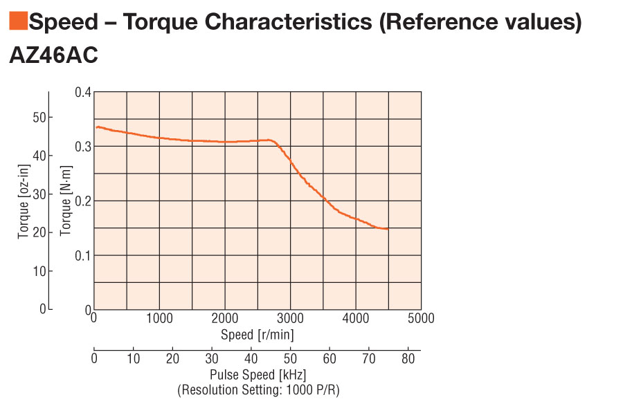 Speed - Torque Characteristics |
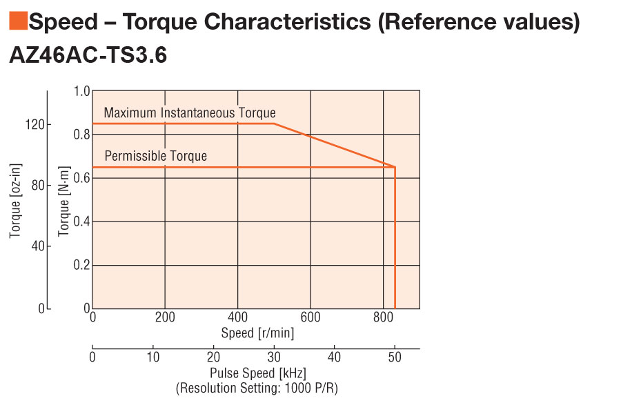
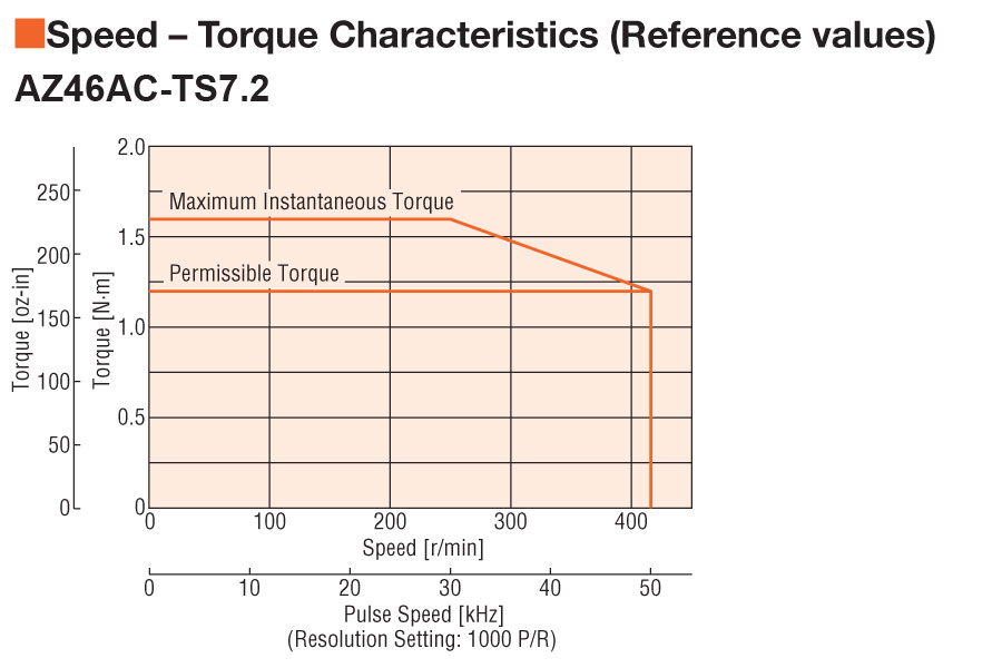
 Speed - Torque Characteristics |
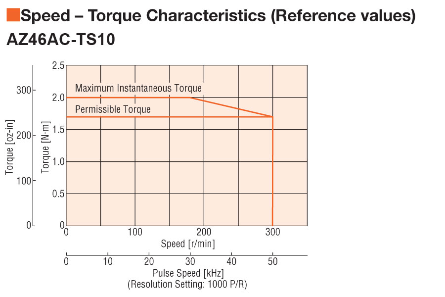
 Speed - Torque Characteristics |
 Speed - Torque Characteristics |
|||||
| Holding Torque | 42 oz-in0.30 N·m | 42 oz-in0.30 N·m | 92 oz-in0.65 N·m | 170 oz-in1.20 N·m | 240 oz-in1.70 N·m | |||||
| Type | Absolute Sensor Type | |||||||||
| Shaft/Gear Type | Round Shaft (No Gearhead) | Round Shaft (No Gearhead) | Taper Hobbed Gear | Taper Hobbed Gear | Taper Hobbed Gear | |||||
| Gear Ratio (X:1) | 3.6 :1 | 7.2 :1 | 10 :1 | |||||||
| Backlash | 2 arc min (0.034º) | 10 arc min (0.17º) | 10 arc min (0.17º) | |||||||
| Shaft | Single | |||||||||
| Electromagnetic Brake | Not Equipped | Equipped | Not Equipped | Not Equipped | Not Equipped | |||||
| Power Supply | Single-Phase 100-120 VAC | |||||||||
| Current | 2.7 A | |||||||||
| Permissible Speed Range (r/min) | 0 ~ 833 | 0 ~ 416 | 0 ~ 300 | |||||||
| Rotor Inertia | 0.30 oz-in²55x10-7 kg·m² | 0.39 oz-in²71x10-7 kg·m² | 0.30 oz-in²55x10-7 kg·m² | 0.30 oz-in²55x10-7 kg·m² | 0.30 oz-in²55x10-7 kg·m² | |||||
| Lost Motion | ||||||||||
| Control Power Supply | 24 VDC ± 5%, 0.25 A |
24 VDC ± 5%, 0.33 A 24 VDC ± 4%, 0.33 A if wiring distance between motor and driver is extended by 65.6 ft. (20 m) using accessory cable. |
24 VDC ± 5%, 0.25 A | 24 VDC ± 5%, 0.25 A | 24 VDC ± 5%, 0.25 A | |||||
| Safety Standards | UL CE | |||||||||
| Radial Load | 0 in. from Shaft End = 7.8 lb0.2 in. from Shaft End = 9.9 lb0.39 in. from Shaft End = 13 lb0.59 in. from Shaft End = 19.1 lb0 mm from Shaft End = 35 N5 mm from Shaft End = 44 N10 mm from Shaft End = 58 N15 mm from Shaft End = 85 N | 0 in. from Shaft End = 7.8 lb0.2 in. from Shaft End = 9.9 lb0.39 in. from Shaft End = 13 lb0.59 in. from Shaft End = 19.1 lb0 mm from Shaft End = 35 N5 mm from Shaft End = 44 N10 mm from Shaft End = 58 N15 mm from Shaft End = 85 N | 0 in. from Shaft End = 4.5 lb0.2 in. from Shaft End = 6.7 lb0.39 in. from Shaft End = 9 lb0.59 in. from Shaft End = 11.2 lb0 mm from Shaft End = 20 N5 mm from Shaft End = 30 N10 mm from Shaft End = 40 N15 mm from Shaft End = 50 N | 0 in. from Shaft End = 4.5 lb0.2 in. from Shaft End = 6.7 lb0.39 in. from Shaft End = 9 lb0.59 in. from Shaft End = 11.2 lb0 mm from Shaft End = 20 N5 mm from Shaft End = 30 N10 mm from Shaft End = 40 N15 mm from Shaft End = 50 N | 0 in. from Shaft End = 4.5 lb0.2 in. from Shaft End = 6.7 lb0.39 in. from Shaft End = 9 lb0.59 in. from Shaft End = 11.2 lb0 mm from Shaft End = 20 N5 mm from Shaft End = 30 N10 mm from Shaft End = 40 N15 mm from Shaft End = 50 N | |||||
| Axial Load | 3.3 lb15 N | |||||||||
| Permissible Moment Load | ||||||||||
|
|
||||||||||