| Lead Time1 | - {Contact your local sales office for more information.} |
Frame Size |
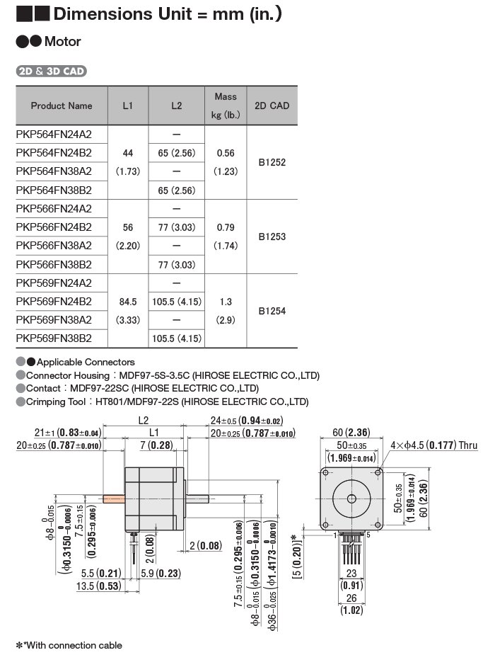
- 2.36 in60 mm |
Motor Length |
- 3.33 in.84.5 mm |
Basic Step Angle |
- 0.72º |
Speed-Torque Characteristics |
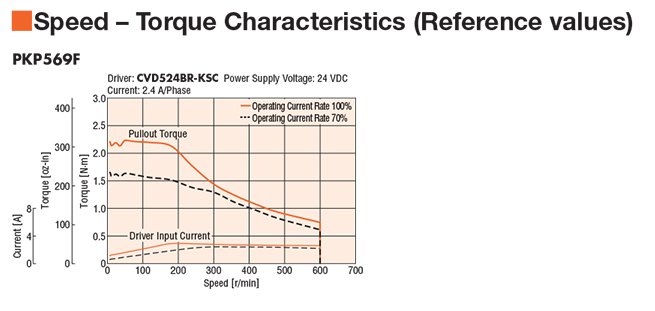
-
 |
Max. Holding Torque |
- 290 oz-in2.1 N·m |
Holding Torque at Motor Standstill |
- 156 oz-in1.1 N·m |
Speed Setting Range |
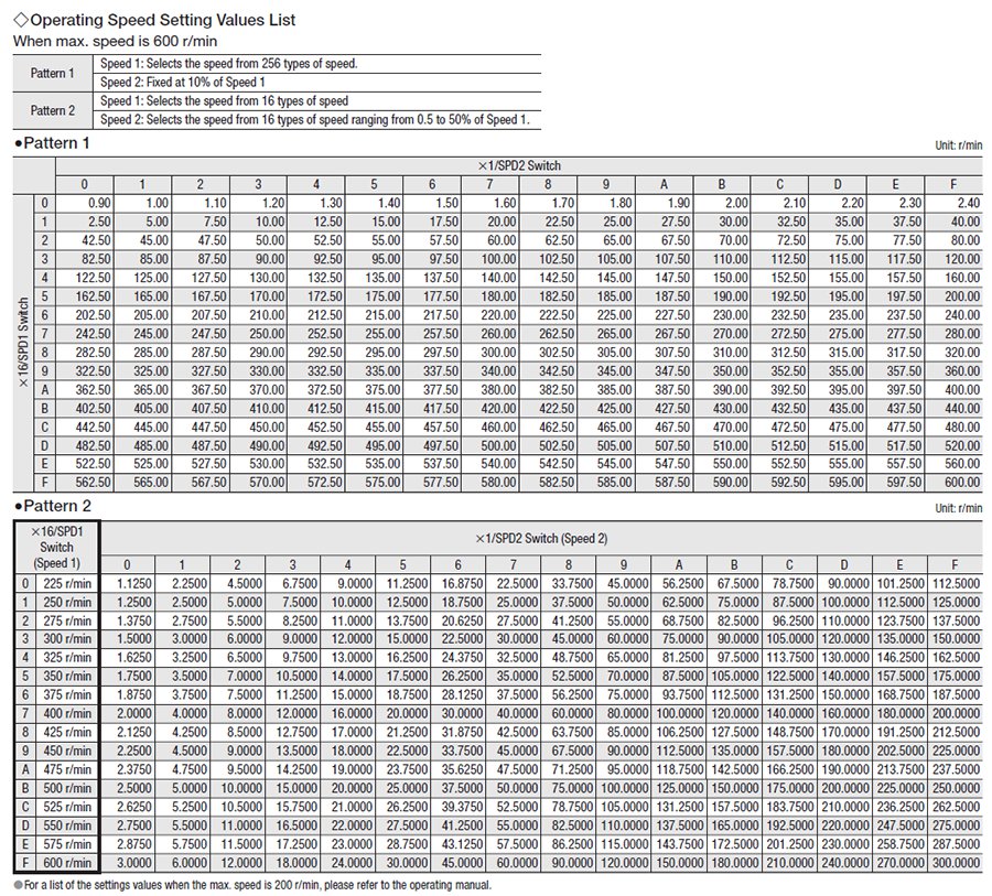
- 0.02 to 600 r/min |
Speed Accuracy |
- ±0.8% |
Power Supply |
- 24 VDC |
Current per Phase |
- 2.4 A/phase |
Shaft/Gear Type |
- Round Shaft with Flat (No Gearhead) |
Gear Type |
- No Gearhead |
Motor Connection Type |
- Flat Connector |
Shaft |
- Single |
Output Shaft |
- Metric |
Output Shaft Diameter |
- 8 mm |
Step Angle |
- 0.72 ° |
Connection Type |
- New Pentagon (Bipolar) |
Lead Wires |
- 5 |
Rotor Inertia |
- 3 oz-in²540x10-7 kg·m² |
Components |
-
CVD524B-KSC, CVD-SC Speed Control Driver ($227.00) PKP569FN24A2, 2.36 in. (60 mm) PKP Series 5-Phase Stepper Motor ($118.00) |
RoHS Compliant |
- These products do not contain substances that exceed the regulation values in the RoHS Directive. |
Safety Standards |
- CE |
California Proposition 65 |
-
⚠ CA WARNING Cancer risk from exposure to Nickel. See www.P65Warnings.ca.gov Risk of reproductive harm from exposure to Di-n-hexyl phthalate (DnHP). See www.P65Warnings.ca.gov Risk of cancer and reproductive harm from exposure to Di(2-ethylhexyl phthalate (DEHP). See www.P65Warnings.ca.gov See "?" or copy/paste www.P65Warnings.ca.gov in your browser. |
Insulation Resistance |
- 100 MΩ or more when 500 VDC megger is applied between the windings and the case under normal ambient temperature and humidity. |
Dielectric Strength |
- No abnormalities are observed, even when applying voltage between the windings and the case for 1 minute under normal ambient temperature and humidity with the following conditions. 1 kVAC 50/60 Hz |
Temperature Rise |
- Winding temperature rise 144ºF (80ºC) max. |
Insulation Class |
- 0 |
Ambient Temperature Range |
- 14 ~ 122ºF (-10 ~ 50ºC) (non-freezing) |
Ambient Humidity |
- 85% or less (Non-condensing) |
Shaft Runout |
- 0.05 mm (0.002 in.) T.I.R. |
Concentricity |
- 0.075 mm (0.003 in.) T.I.R. |
Perpendicularity |
- 0.075 mm (0.003 in.) T.I.R. |
Radial Play |
- 0.025 mm (0.001 in.) maximum of 5 N (1.12 lb.) |
Axial Play |
- 0.075 mm (0.003 in.) maximum of 10 N (2.2 lb.) |
Radial Load |
- 0 in. from Shaft End = 20 lb0.2 in. from Shaft End = 22 lb0.39 in. from Shaft End = 29 lb0.59 in. from Shaft End = 40 lb0.79 in. from Shaft End = 60 lb0 mm. from Shaft End = 90 N5 mm from Shaft End = 100 N10 mm from Shaft End = 130 N15 mm from Shaft End = 180 N20 mm from Shaft End = 270 N |
Axial Load |
- 6.7 lb30 N |
Dimensions |
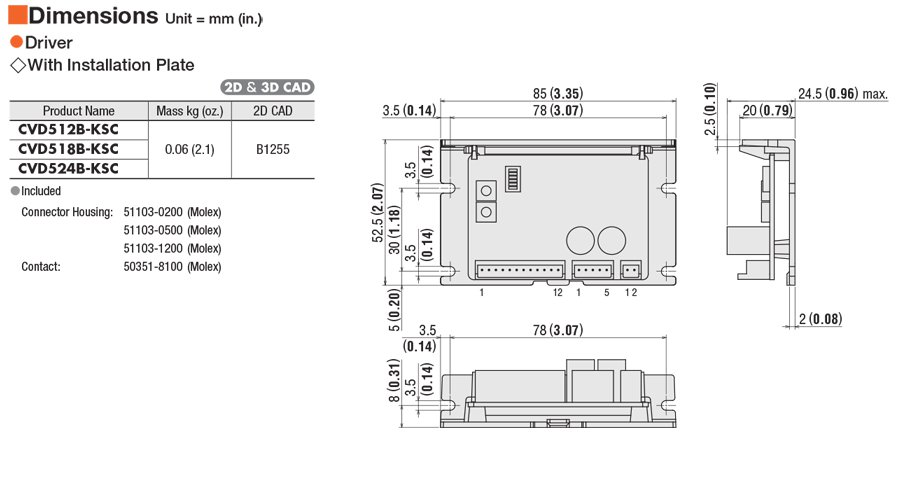
-
  |
Performance |
-
  |
Connection |
-
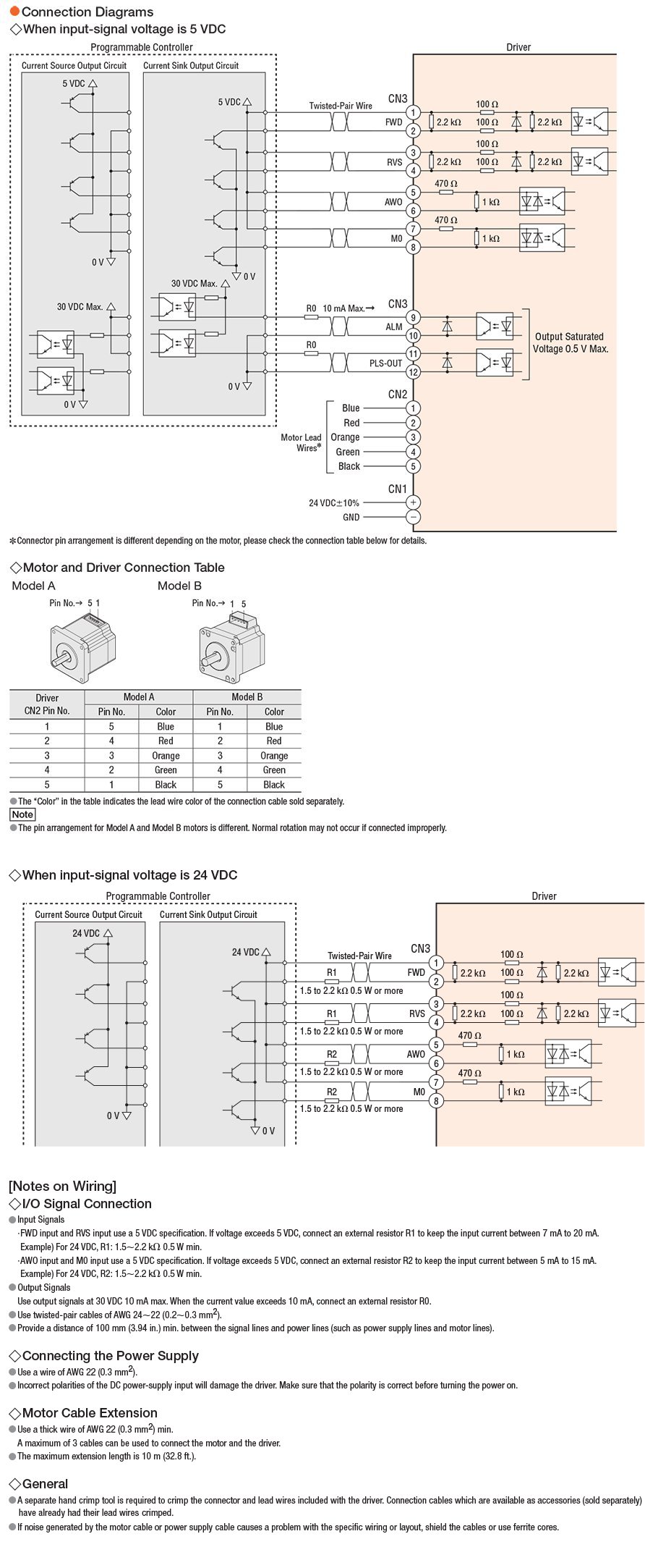 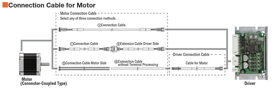 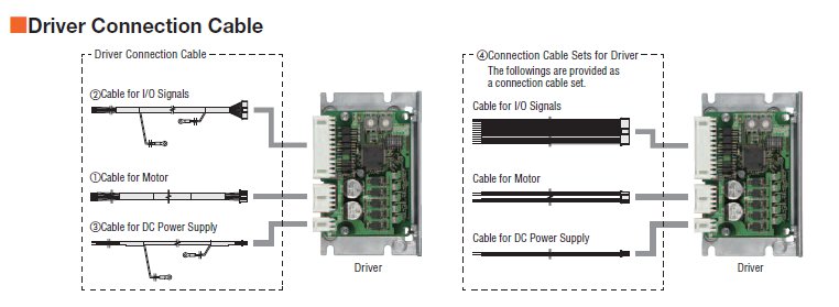 |
System |
-
  |